


Wireless power is going to introduce significant innovations in kitchens, making them smarter, sleeker and more space efficient. Appliances from simple low-power juicers to blenders or kettles, and other that require up to 2.2 kW of power will benefit by eliminating power cords thanks to the new standard “Ki Cordless Kitchen” that is set to be released by the Wireless Power Consortium.
The key driver of rapid adoption is interoperability. All certified Ki transmitters and appliances will follow defined safety protocols and work with each other, regardless of the brand, device type, or version of Ki they use.
The Ki transmitter can also be considered a smart induction cooktop that will not only power Ki receivers but also operate standard induction utensils like heating a pan.
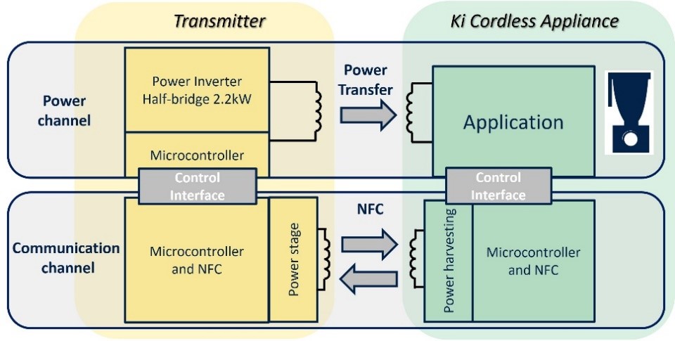
Ki enables smart communication between transmitter and appliances based on Near Field Communication (NFC) providing auxiliary power, bi-directional data paths, advanced control features, authentication and protections (FOD) and it is essential for interoperability. The block diagram of the Ki Cordless Kitchen concept block diagram is highlighted in Figure 1.
STMicroelectronics, a global semiconductor leader serving customers across the wide spectrum of electronics applications, has been participating in the Ki Cordless Kitchen standard since the beginning and is ready with the Ki Cordless Kitchen power transmitter reference design i.e. STEVAL-KITXCB.
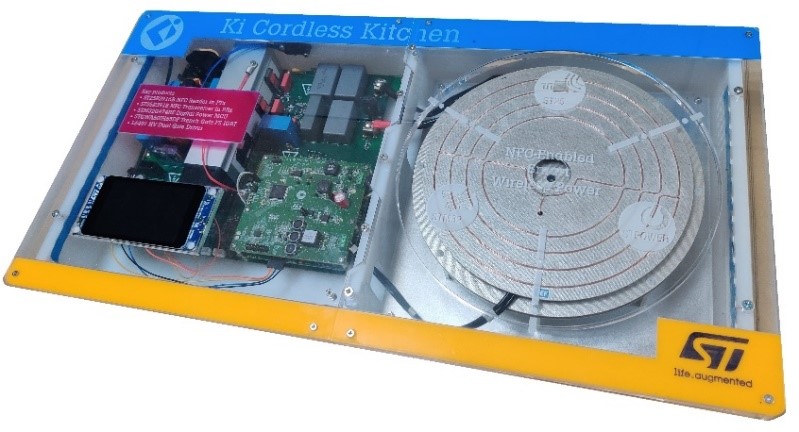
The STEVAL-KITXCB reference design consists of a power inverter board, auxiliary power supply board, an NFC board, inverter microcontroller board, a power coil, NFC antenna and GUI display board as shown in Figure 2. Thanks to the modular design approach, it is easy for users to test and debug the various sections involved.
The main power board comprises an inverter stage based on half-bridge topology. The IGBTs during power transfer switch between 26 to 74 kHz.
The power inverter board is connected to a power coil and is digitally controlled by the STM32G474RET6 microcontroller, which specifically addresses the needs of digital power conversion applications thanks to the High-resolution timer peripheral and a rich and advanced integrated analog.
The NFC communication between the Ki transmitter and Ki receiver is managed by ST25R3916, high performance NFC universal device which is mounted on a dedicated daughter card. The NFC antenna is connected to the NFC daughter card.
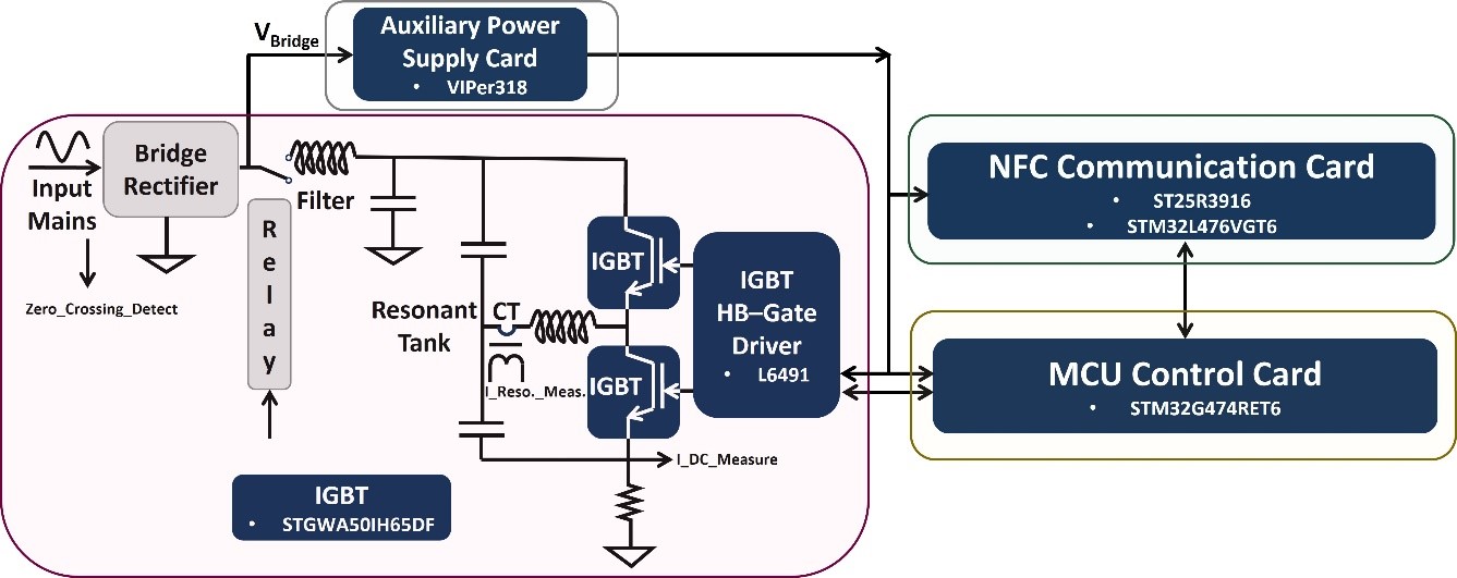
The auxiliary power supply is managed by an off-line flyback circuitry based on VIPer318, high voltage converter ensuring compactness and very low standby consumption to generate 24V DC. The interconnection between the main power inverter board and the daughter cards of the evaluation kit is shown in Figure 3.
The inverter stage is based on STGWA50IH65DF trench gate field-stop 650 V IH series IGBT, featuring very low Vcesat and Eoff to ensure high efficiency at high switching frequency and supported by the robust half-bridge gate driver L6491D, provided with high driving current source and sink capability.
The Ki Kitchen standard protocol is managed by a dedicated STM32L476VGT64 microcontroller mounted on an NFC daughter card and it communicates over UART with the STM32G474RET6 microcontroller, which is managing power inverter stage. During startup when the Ki receiver/appliance is brought on top of induction hub the Ki transmitter will supply the initial energy to power the User interface of the appliance through NFC and establish a communication carrier as shown in Figure 4.
And when the Ki receiver/appliance is switched ON (requesting power from the Ki transmitter) from its user interface, then the auxiliary power transfer from NFC stops, and the power inverter of the Ki transmitter transmits the power including auxiliary power to the Ki receiver via the principle of induction.
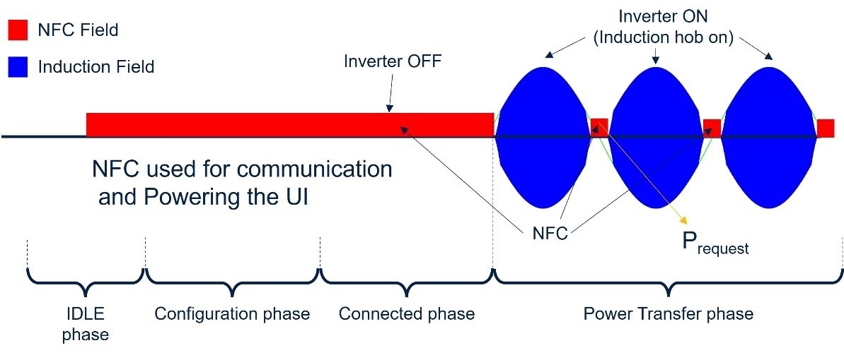
To prevent interference between NFC and wireless induction power transfer during the power transfer state, the wireless induction power transfer is switched completely off during the mains crossing and NFC becomes active as shown in Figure 4.
Ki Receiver vs Induction Utensil (Pan/Pot)
The standard induction utensils are made of ferromagnetic materials. The bottom of an induction utensil (pan/pot) can be treated as an induction coil with one winding and low load resistance where received power is dissipated.
So, the power transmitter coil and utensil can be considered a transformer in which the induction utensil acts as a shorted secondary (load). An alternating current is made to flow through the transmitter resonant power coil, which leads to the generation of an oscillating magnetic field. The magnetic field induces an electric current inside the induction utensil.
The Ki receiver mainly consists of a resonant power coil, resonant capacitor, NFC circuitry and Ki receiver/appliance circuitry. For the Ki transmitter the power coil is fixed but for the Ki receivers, the size of the power coil varies depending on the power requirements.
To maximize the energy transfer, the Ki receiver must be tuned to the transmitter’s resonant frequency. Now, there will be two resonance points: one of the Ki transmitter and the other of the Ki receiver.
To have better efficiency, the transmitter needs to operate at a second resonant frequency, but that doesn’t guarantee the maximum power required by the Ki receiver. To transmit the desired power the Ki transmitter needs to shift to the first resonant frequency. The resonant shift is managed by the STM32G474RET6 microcontroller control algorithm.
To shorten the development time and let customers evaluate products in the final application, STMicroelectronics offers a reference design (STEVAL-KITXCB) for the transmitter and is working on the reference design for the different types of receivers. The hardware design files and firmware source code are available with developer-friendly license terms. For more details, please contact the STMicroelectronics sales office.
AUTHORS
- Akshat JAIN: STMicroelectronics INDIA
- Fabrizio Di FRANCO: STMicroelectronics ITALY
- Martin DENDA, Rene WUTTE: STMicroelectronics AUSTRIA
- Bruno TISSERAND: STMicroelectronics FRANCE
