


When it comes to surface-mount technology (SMT) components, solder has long reigned supreme in terms of popularity. As such, most of the publications that address board mounting techniques focus on optimizing the various solder attachment methods available, including hand soldering, wave soldering, hard soldering, soft soldering, silver soldering, brazing, solder balling, and reflow soldering, the latter of which can be further broken down into infrared (IR) reflow, vapor phase reflow, and hot air convection reflow soldering.
In fact, the literature about solder attachments is so pervasive that many engineers aren’t even aware of alternatives like conductive epoxy attachments, which enable comparatively durable and reliable component-to-board connections.
A Brief Introduction to Conductive Epoxy Attachment
Electrically conductive epoxy assembly methods have been utilized in a series of niche electronics industry applications, including microelectronics, lead frames, and hybrid microcircuits, for several decades now. Despite this fact, a number of engineers either aren’t aware of or sufficiently knowledgeable about this solder attachment alternative.
Conductive epoxies are commonly one- or two-part adhesive epoxy or silicone compound imbued with electrically conductive metals — typically silver; although, nickel, copper, palladium, and gold options are available as well.
To use them, you simply dispense the adhesive onto a PCB’s SMT pads using a pneumatic needle, press a component into the epoxy-coated pads, and cure the assembly via either a specific amount of time and temperature or an ultraviolet (UV) light. When the epoxy cures, its volume shrinks, which causes the metal particles to make contact with both the component and the board and creates a conduction path.
Advantages of Conductive Epoxy Attachments
Although there aren’t as many conductive epoxy suppliers as solder process suppliers, conductive epoxy offers several advantages over solder attachments. For one, conductive epoxy attachments are much more environmentally friendly than the standard tin/lead (SnPb) soldering process.1
And while the sustainability improvements they offer are comparable to those offered by lead-free soldering processes, conductive epoxy attachments require a much simpler and less capital-intensive process compared to lead-free solder attachments. Another advantage is that the conductive epoxy attachment process subjects components to significantly lower levels of thermal-induced stress than soldering processes.
Conductive epoxy attachments also provide all components with compliant connections to the substrate, which increases their resistance to hazards including shock, vibration, thermal cycling, and mechanically induced strain.
In addition, conductive epoxy attachments eliminate the micro-cracking concerns common to lead-free solder processes since lead-free solder is typically less elastic than lead-based solder.
Disadvantages of Conductive Epoxy Attachments
From a reliability point of view, epoxies exhibit increased resistance as they age. They alsohave unstable moisture performance and varying environmental performance capabilities with regard to lifetimes, temperature, humidity, vibration, and shock, which can discourage their use in a number of application areas.
Process and assembly concerns range from increased difficulty of dispensing and rework, air entrapment in the epoxy, less self-alignment for fine pitch components, and much lower heat conduction than solder-based terminations.
However, vertical pneumatic dispensers commonly solve any dispensing difficulties, and many of these concerns diminish when conductive epoxy is used in hybrid microcircuits with hermetically sealed ceramic packages and controlled atmospheres.
Conductive Epoxy Selection Tips
There are several characteristics to consider when selecting a conductive epoxy. First, there’s the formulation.
Conductive epoxies are available in a variety of different carrier formulas, including one-part epoxy, two-part epoxy, and silicone-based epoxy — all of which are designed to suspend the conductive metal particles until they are dispensed and cured — and each carrier type dramatically affects the lead attachment, attachment integrity, and system performance.
One-part epoxies don’t have to be mixed before you use them, which simplifies the process and provides some time and cost savings, but most must be refrigerated before use and require relatively high temperatures — on the order of 150°C — to cure. Two-part epoxies often cure at temperatures as low as room temperature, which eliminates the need for cold storage, but they have a short working time before curing, and they require great care when mixing the two parts together to ensure proper ratios.
Other characteristics that end-users should consider when evaluating epoxies include the physical, electrical, and reliability requirements of their application, such as resistivity, shear adhesion, impact resistance, and environmental performance specifications, as well as the ease of processing.
Typical minimum acceptable requirements for conductive epoxies include a volume resistivity less than or equal to one milliohm-centimeter (1m?-cm) and a less than 20% shift in contact resistance after 500 hours at 85°C, 85% relative humidity (RH), and adequate impact resistance.3
SMT Components Compatible With Conductive Epoxies
Although not all SMT component terminations are compatible with conductive epoxy attachment — tin (Sn) and tin/lead (Sn/Pb) terminations for instance — there are a wide variety of SMT components that are, including components with titantium/tungsten/gold (Ti/W/Au), titanium/tungsten/nickel (Ti/W/Ni), silver/palladium (AgPd), copper/gold (CuAu), nickel/gold (NiAu), electroless nickel immersion gold (ENIG), and electroless nickel/electroless palladium immersion gold (ENEPIG) terminations.
SMT components with RoHS-compliant tin and tin/lead terminations aren’t compatible with conductive epoxy attachments for two main reasons. The first is that conductive epoxies absorb water, and the absorption would cause the tin-plated layer to oxidize, which would eventually increase the component’s contact resistance and heating losses relative to the substrate. The second is that conductive epoxy attachments can cause microcracks in tin-terminated SMT components and diminish the shear strength of the part to the mounting pads.
Luckily, there are a number of compatible termination technologies, including RoHS-compliant ones like ENIG and ENEPIG, which are both widely employed for the slate of benefits they offer, such as excellent joint solderability, high electrical conductivity, and corrosion resistance.
Conductive Epoxy Attachment Considerations
It’s important to note, however, that even though there’s a variety of SMT components compatible with conductive epoxy attachments and this method offers several advantages over solder attachments — including greater sustainability, less thermal-induced stress, increased environmental resistance, and imperviousness to micro-cracking — compatibility doesn’t necessarily equate to suitability.
For instance, miniature SMT components, such as 0201 and 01005 multilayer ceramic capacitors (MLCCs), and SMT components with complex, high-density terminations, such as eight-terminal 0306 MLCCs, are compatible with conductive epoxy attachment if the proper termination metallization is used but might be better served by solder attachments due to curing and alignment characteristics.
For example, when using conductive epoxy attachment methods on miniature and complex, high-density SMT components, optimal flow control and dispensing needle orientation are key since conductive epoxies cure without moving and flowing and exhibit a thinning tail characteristic that can result in excess epoxy, bridge the terminations, and create a short once the component is placed.
Another reason that conductive epoxy might not be ideal for these types of components is that components don’t self-align in conductive epoxy as they do in solder processes, so you must use extreme care to ensure the proper alignment of the component on the mounting pads, which can be more challenging with such small and complex components.
FLEXITERM and FLEXISAFE MLCCs: An Alternative to the Alternative
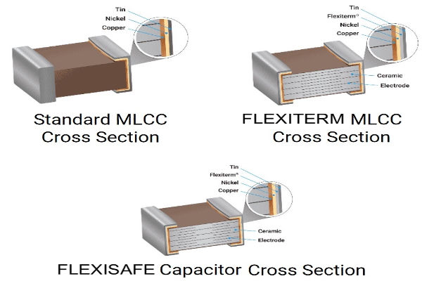
If the performance advantages of conductive epoxy attachments are more attractive to you than the sustainability factor, which can be duplicated with lead-free solder processes — albeit with a bit more complexity and capital investment in processing equipment — you can also consider FLEXITERM® and FLEXISAFE™ MLCCs from KYOCERA AVX.
FLEXITERM MLCCs incorporate a conductive epoxy layer under the final metal termination finish that — while different than and not compatible with the conductive epoxy used for terminations — also provides a compliant termination that acts as a shock absorber, reliably withstands the strain resulting from temperature cycling, depanelization, shock and vibration, and bending, and prevents internal cracking.
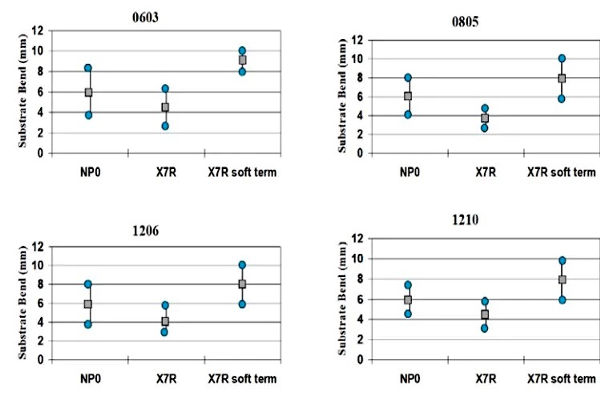
FLEXITERM MLCCs can withstand 5mm of flexure without any internal cracking in addition to 3,000 or more temperature cycles. FLEXISAFE MLCCs combine the award-winning FLEXITERM layer with the cascade design previously used for high-voltage MLCCs to protect the components from low insulation resistance failures resulting from other causes of failure, such as thermal stress damage, repetitive strike electrostatic discharge (ESD) damage, and placement damage, which is ideal for applications that require industry-leading safety features. In addition, neither exhibits increased equivalent series resistance (ESR) or ESR instability in response to time, moisture, or temperature, and both are approved to MIL-PRF-32535, National Aeronautics and Space Administration (NASA) and European Space Agency (ESA) standards.
Closing
Although solder processes are the most prolific SMT component attachment methods, it’s important to be knowledgeable about alternative options, like conductive epoxy attachment, and the various benefits that they provide in order to ensure that you select the best possible attachment methods for your application.
While there are certainly both pros and cons to conductive epoxy attachment, as there are for virtually every design decision one can make, as well as a variety of both compatible and incompatible components, conductive epoxy attachment offers a very low-stress, low-temperature attachment method for creating end circuity and can be especially beneficial for microelectronics, lead frames, and hybrid microcircuits with hermetically sealed ceramic packages.
And if the compliant terminations of conductive epoxy attachments are appealing but the cons or compatibility issues are holding you back, component solutions like KYOCERA AVX FLEXITERM and FLEXISAFE MLCCs might provide you with a suitable alternative to this alternative attachment method that’s more compatible with your design.
References
- Li, Li and Morris, J.E. “An Introduction to Electrically Conductive Adhesives,” Portland State University,1998, https://web.cecs.pdx.edu/~jmorris/Research%20%26%20Publications/Electrically%20Conductive%20Adhesives/Int%20J%20Microelectronics%20Packaging%201%20(1998)%20159%20ICA%20Introduction.pdf.
- Salisbury, Ian. “Thermal Management of Surface Mounted Tantalum Capacitors,” KYOCERA AVX technical paper, https://www.kyocera-avx.com/news/thermal-management-of-surface-mounted-tantalum-capacitors/.
- Small, Darryl J. “Reliability Considerations of Electrically Conductive Adhesives,” Loctite Corporation technical paper, 2002. ResearchGate, https://www.researchgate.net/publication/3940842_Reliability_of_electrically_conductive_adhesives.
About The Authors

Ron Demcko is a KYOCERA AVX senior fellow at KYOCERA AVX headquarters in Fountain Inn, South Carolina. This role centers on projects ranging from simulation models for passive components to product support, new product identification, and applied development.
Prior to this role, Ron was the EMC Lab Manager at AVX in Raleigh North Carolina. This lab concentrated on subassembly testing and passive component solutions for harsh electrical and environmental applications. Before that, he was an AVX application engineer for products including integrated passive components, EMI filters, and transient voltage suppression devices.
Prior to joining AVX, Ron worked as a product engineer and, later, a product engineering manager in the electronics division at Corning Glass Works. In these roles, he supported the development, production, and sale of pulse-resistant capacitors, high-temperature capacitors, and radiation-resistant capacitors, developed high-frequency test methods, and co-developed high-temperature test systems. Ron earned his BSEE from Clarkson College of Technology (now Clarkson University). He can be reached at ron.demcko@kyocera-avx.com.

Ashley Stanziola has been a KYOCERA AVX field application engineer at KYOCERA AVX headquarters in Fountain Inn, S.C. for five years. This role centers on projects ranging from simulation models, product support, new application identification, and new product introductions.
Prior to this role, Ashley earned her bachelor’s degree in electrical engineering at Clemson University. She can be reached at ashley.stanziola@kyocera-avx.com.