Electric vehicles (EVs) place demanding requirements on their on-board charging systems, particularly when it comes to protecting sensitive power electronics from voltage transients and surge events. Because the on-board charger (OBC) interfaces directly with the AC power grid, it must withstand disturbances that range from routine switching transients to high-energy surge pulses caused by lightning or grid faults.
Selecting the right surge protection strategy is therefore essential to ensuring long-term reliability and system robustness.
Designers have traditionally relied on metal oxide varistors (MOVs) for transient voltage suppression. While MOVs are effective and widely used, higher surge requirements and tighter semiconductor voltage limits are driving interest in alternative protection architectures that offer lower clamping voltage and improved stability over time.
One such approach combines a SIDACtor® protection thyristor with an MOV to enhance overall surge performance in EV on-board chargers.
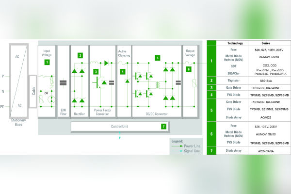
Figure 1. On-board charger block diagram
Surge Exposure in EV On-Board Chargers
During charging, the EV On-Board Chargers is exposed to overvoltage events originating on the power grid. If these transients exceed the maximum voltage ratings of downstream power semiconductors, permanent damage can occur.
As EV architectures evolve, engineers must accommodate increasing surge current requirements while simultaneously reducing clamping voltage to protect increasingly dense and efficient power conversion stages.
Figure 1 illustrates the functional blocks of a typical on-board charger and highlights the sections most vulnerable to surge stress, particularly on the AC input and primary power conversion stages. These areas require carefully selected protection components to balance performance, cost, and board space.
Surge pulses affecting the OBC may arise from several sources, including indirect lightning strikes, load switching events, and system faults.
While a direct lightning strike can reach currents on the order of 100 kA, even indirect events can impose severe stress on grid-connected electronics.
Common contributors to transient surges include:
Switching of capacitive loads
Switching within low-voltage or resonant circuits
Short circuits caused by construction activity, traffic accidents, or storms
Operation of fuses and other overvoltage protection devices
These surges can couple into a system capacitively between parallel conductors, inductively through current loops, or via near-field electromagnetic radiation.
They may propagate along power, data, or signal lines and appear either symmetrically (line-to-line) or asymmetrically (line-to-ground). Understanding both the coupling mechanism and propagation path is essential to implementing an effective protection strategy.
Surge Standards and Design Implications
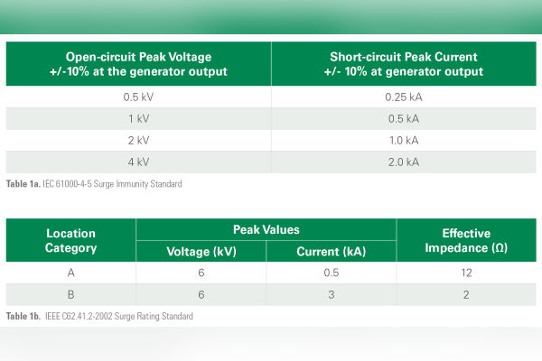
International and regional standards define the surge levels that grid-connected equipment must withstand. IEC 61000-4-5 specifies surge immunity levels up to 4 kV, corresponding to surge currents of up to 2 kA with a 2-ohm generator.
In contrast, IEEE C62.41.2-2002 defines a more demanding 6 kV/3 kA surge requirement, which today governs most power grid–related AC circuits.
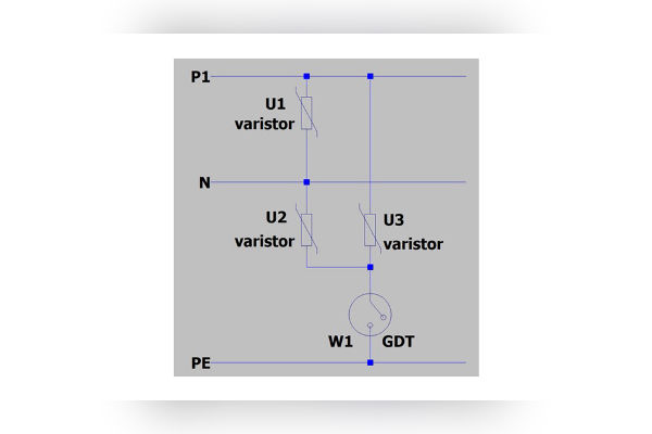
Table 1. (1a) IEC 61000-4-5 peak voltage and peak current withstand ratings and (1b) IEEE C62.41.2-2002 Standard 1.2/50 µs-8/20 µs, expected voltages and current surges.Figure 2. Recommended circuit for differential and common mode transient voltage circuit protection using MOVs and a GDT.
To meet these higher requirements, many designers place MOVs on the AC primary side of the charger. While 14-mm MOVs are commonly used, larger 20-mm MOVs are often preferred for improved reliability.
A 20-mm MOV can typically withstand on the order of 45 pulses of a 6 kV/3 kA surge, compared with roughly 14 such events for a 14-mm device.
Figure 2 shows a representative protection configuration using MOVs and a gas discharge tube (GDT) to address both differential-mode and common-mode transients.
Comparing MOV and SIDACtor+MOV Performance
Although MOVs provide effective voltage clamping, their performance can be limited under repeated surge exposure.
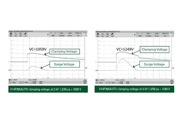
Figure 3 illustrates the clamping behavior of a 14-mm MOV subjected to 2 kV and 4 kV surge pulses. With a maximum operating voltage of 385 VAC RMS, the MOV clamps at voltages exceeding 1000 V—levels that impose significant electrical stress on downstream power semiconductors.
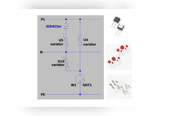
An alternative approach places a SIDACtor protection thyristor in series with an MOV.
Figure 4 shows this configuration for protection between line and neutral. In this arrangement, the SIDACtor acts as a crowbar device during high-energy transients, redirecting surge current and enabling the use of an MOV with a lower nominal voltage rating.
Figure 3. SIDACtor + MOV Transient Voltage Performance
Figure 4. SIDACtor+MOV protection from voltage transients between line and neutral
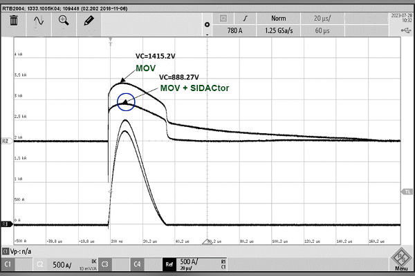
Measured results highlight the benefit of this combination. For a 6 kV/3 kA surge, the SIDACtor+MOV configuration clamps the voltage to below 1000 V, whereas an MOV alone exceeds this level.
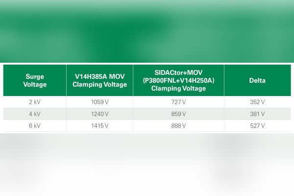
Table 2 compares clamping voltages for a standalone MOV and a SIDACtor+MOV combination across multiple surge amplitudes, demonstrating reductions of several hundred volts when the SIDACtor is added.
Figure 5 further illustrates the voltage-versus-time response of the two approaches, showing that the SIDACtor+MOV combination not only clamps at a lower peak voltage but also maintains more consistent behavior across surge events.
Table 2. Clamping voltage of a Littelfuse V14H385A MOV compared with P3800FNL SIDACtor and a V14H250A MOV under different surge voltage.Figure 5. Response of the MOV and the SIDACtor+MOV combination to a 6kV surge
Reliability Considerations
Repeated surge exposure causes gradual changes in MOV characteristics. Leakage current tends to increase, and breakdown voltage may decrease as the device absorbs multiple high-energy pulses.
To compensate, designers often select larger MOVs, which increases cost and consumes valuable PCB area.
In a SIDACtor+MOV configuration, overall protection performance remains more stable because the SIDACtor limits leakage current and reduces electrical stress on the MOV during surge events.
This helps preserve clamping behavior over time and supports more robust long-term operation in harsh automotive environments.
A Practical Path Forward for EV OBC Protection
MOVs remain a proven solution for transient voltage suppression, but evolving EV charger requirements are pushing designers toward protection schemes with lower clamping voltage and improved stability.
By combining a SIDACtor protection thyristor with an MOV, engineers can reduce stress on power semiconductors, limit leakage current, and achieve a more robust surge protection strategy without excessive increases in size or cost.
For applications where compliance with high-energy surge standards and long-term reliability are critical, the SIDACtor+MOV approach offers a compelling alternative to standalone MOV protection.
The Volt Team is The Volt Post’s internal Editorial and Social Media Team. Primarily the team’s stint is to track the current development of the Tech B2B ecosystem. It is also responsible for checking the pulse of the emerging tech sectors and featuring real-time News, Views and Vantages.


